FOOT STEP POWER GENERATOR FOR MOBILE CHARGING
CHAPTER
1
INTRODUCTION
1.1 Project Introduction -
Energy
is nothing but the ability to do work. Power has turned into help for the human
populace nowadays. Its request is expanding rapidly. In day to day, life
innovation needs an immense measure of electrical power for its different
activities. Power generation is the single largest wellspring of contamination
in the world. Due to which numerous energy resources are produced and wasted.
Electricity is generally generated from resources like water, wind, coal, etc.
for generating the electricity from these resources development of big plants
that are needed having high maintenance and high cost. In like manner, it is
the target of the present development to give the technique for electrical
power generation from which regularly expanding human populace that does not
adversely affect the natural resources. Our project depends on a rule called
the piezoelectric effect impact, in which certain materials can develop an
electrical charge from having weight, the strain applied to them. The
piezoelectric effect is the effect of specific materials to generate the
electric charge in response to applied mechanical stress on it. It is the
effect in which mechanical vibrations, pressure or strain applied to the
piezoelectric material are converted into electrical form. Piezoelectricity
alludes to the capacity of a few materials to produce an electric potential in
light of connected weight. The inserted piezoelectric material can give the
enchantment of the changing overweight applied by moving individuals into the
electric current, which is stored in a battery and further distributed using
RFID cards. The current is distributed using (radio-frequency identification)
RFID cards so that only an authorized person can use the generator for
charging. Thus we charge a battery using power from footsteps, display it on
LCD using a microcontroller circuit and allow for mobile charging through the
setup. Our project model cost is effective and easy to implement and also it is
green and not harmful to the environment.
CHAPTER
NO.2
2.
BLOCK DIAGRAM& EXPLAINATION

Fig- 2Block diagram
The following figure shows the block diagram of an footstep power generator using RFID for charging. After applying weight on piezoelectric plates voltage is developed across the plates. That voltage is applied to the battery for charging purposes. This is then provided to our monitoring circuitry.LCD is interfaced with a piezo sensor using a microcontroller that allows the user to monitor the voltage and charges a connected battery by it. Also,it consists of a USB mobile phone charging point where the user may connect cables to charge the mobile phone from the battery charge.
The block diagram consists of following parts-
2.1
MICROCONTROLLER –
Microcontroller ATmega328 is an 8-bit and 28 Pins AVR Microcontroller, manufactured by Microchip, follows RISC Architecure and has
a flash type program memory of 32KB.It has an EEPROM memory of 1KB and its SRAM
memory is of 2KB. It is mostly used in arudino uno. The microcontroller which
is used to monitors the voltage that charges the rechargeable battery. It then,
displays the amount of charging on the LCD. The microcontroller also helps
controlling charging and discharging of the battery to protect it from over
charging and avoiding the damage could be caused.

Fig-2.1.1 Microcontroller
2.2 PIEZOELECTRIC
SENSOR-
The Piezo electrical sensors are placed under insulating
material (platform) and pressure is created by footstep. The property of
piezoelectric material is to generate electricity when we apply pressure. It
gives an amount of output voltage that varies than the other when pressure is
applied.These sensors are mainly used for process control, quality assurance,
research and development in various industries. The applications of this sensor
involve, aerospace, medical, nuclear instrumentation, and as a pressure sensor
it is used in the touch pad of mobile phones.

Fig-2.2.1 Piezoelectric sensor
2.3 BATTERY
Battery (electricity), an array of electrochemical cells for
electricity storage, either individually linked or individually linked and
housed in a single unit. An electrical battery is a combination of one or more electrochemical
cells, used to convert stored chemical energy into electrical energy. Batteries
may be used once and discarded, or recharged for years as in standby power
applications.Lead-acid batteries are the most common in PV systems because
their initial cost is lower. Lead acid batteries are reliable and cost
effective with an exceptionally long life. The Lead acid batteries have high
reliability because of their ability to withstand overcharge, over discharge
vibration and shock. The use of special sealing techniques ensures that our
batteries are leak proof and non-spoilable. The batteries have exceptional
charge acceptance, large.The system battery consists of electrochemical cells
to store electricity in a single unit. Some batteries are used once and some of
them are rechargeable. Here we need a rechargeable one to be able to charge it
again when it's empty after consuming it by users.

Fig –
2.3.1 Battery
2.4 VOLTAGE
SAMPLER-
Voltage Sampler or sample and hold circuit is an essential
analog building block and the applications of voltage sampler includes switched
capacitor filters and analog-to-digital converters. The main function of the
sample and hold circuit is to sample an analog i/p signal and hold this value
over a particular length of time for subsequent processing. Sample and hold
circuit is designed using only one capacitor and one MOS transistor. The
working of this circuit is straight forward. When CK is high, then the MOS
switch will be ON, which in turn permits output voltage to track input voltage.
When CK low, then the MOS switch will be OFF.

Fig -
2.4.1 Voltage Sampler
2.5 LCD DISPLAY-
There are many choices for LCD like: 2x40 without
backlighting, 1x16 which has only one row to show and finally 2x16 which is the
most common type that can cover the system needs in very simple way. The LCD is
interfaced with the microcontroller to display the battery voltages and the
number of steps.

Fig –
2.5.1 Lcd Display
2.6 POWER SUPPLY-
Here we are using an adapter of 12Vand 1A as a power supply
to turn on the system.This adapter contains a transformer to convert the mains
electricity voltage (220V) to a lower voltage (12V), a rectifier to convert it
to pulsating DC, and a filter to smooth the pulsating waveform to DC, with
residual ripple variations small enough to leave the powered device unaffected.
CHAPTER NO.3
3. CIRCUIT DIAGRAM

Fig-3.1
Circuit Diagram
The
schematic diagram is shown in above figure. A tile made up of piezo material generates
voltage across a piezo tile which is supplied to a bridge rectifier circuit to
obtained DC voltage and given to a rechargeable battery and thus the battery
gets charged and this can be used to drive DC loads. The battery used here is a
Lead Acid Battery of 6V. A LCD is interfaced with microcontroller. The
microcontroller used here is ATMEGA 328P which is 8-bit,32kb flash with 1k RAM
and has 16MHz speed. The 16 x 2 LCD is used to display the voltage generated by
the piezo-electric tile. The crystal oscillator is connected to microcontroller
which is used to give clock signal. The power supply unit is used to supply
power to microcontroller and LCD. This unit consist of an IC called IC7805
which will convert the 12V to 5V.
CHAPTER NO. 4
4.
COMPONENT DESCRIPTION
4.1 MICRO CONTROLLER:
The ATmega328 is
a single-chip microcontroller created by Atmel in
the megaAVR family (later Microchip Technology acquired
Atmel in 2016). It has a modified Harvard
architecture 8-bit RISC processor core.
An ATMega Microcontroller is an 8-bit microcontroller with
Reduced Instruction Set (RISC) based Harvard Architecture. God to know: As the
name suggest, for instance, “ATmega16″ , where AT = Atmel, mega = mega AVR and
16= 16kb flash memory.
SPECIFICATIONS
OF ATMEGA MICROCONTROLLER:
The Atmel 8-bit AVR RISC-based microcontroller
combines 32 KB ISP flash memory with read-while-write
capabilities, 1 KB EEPROM, 2 KB SRAM, 23 general purpose
I/O lines, 32 general purpose working registers, three flexible
timer/counters with compare modes, internal and external interrupts,
serial programmable USART, a byte-oriented 2-wire serial
interface, SPI serial port, 6-channel 10-bit A/D
converter (8-channels in TQFP and QFN/MLF packages),
programmable watchdog timer with internal oscillator, and five
software selectable power saving modes. The device operates between 1.8-5.5
volts. The device achieves throughput approaching 1 MIPS per MHz
4.2
PIEZOELECTRIC SENSORS:
A piezoelectric
sensor is a device that uses the piezoelectric effect to
measure changes
in pressure, acceleration, temperature, strain,
or force by converting them to an electrical charge. The
prefix piezo- is Greek for 'press' or 'squeeze'.
PRINCIPLE
OF OPERATION:
The way a piezoelectric material is cut defines one of
its three main operational modes:
·
Transverse
·
Longitudinal
·
Shear.
TRANSVERSE EFFECT
A
force applied along a neutral axis (y) displaces charges along the (x)
direction, perpendicular to the line of force. The amount of charge depends on the geometrical dimensions
of the respective piezoelectric element. When dimensions apply,where is the dimension in line
with the neutral axis, is
in line with the charge generating axis and is the corresponding piezoelectric
coefficient.
LONGITUDINAL EFFECT
The
amount of charge displaced is strictly proportional to the applied force and
independent of the piezoelectric element size and shape. Putting several elements
mechanically in series and electrically in parallel is
the only way to increase the charge output. The resulting charge iswhere is the piezoelectric
coefficient for a charge in x-direction released by forces applied along
x-direction(in pC/N). is the applied Force in
x-direction [N] and corresponds
to the number of stacked elements.
SHEAR EFFECT
The
charge produced is exactly proportional to the applied force and is generated
at a right angle to the force. The charge is independent of the element size
and shape. For elements
mechanically in series and electrically in parallel the charge isIn contrast to the longitudinal and shear
effects, the transverse effect make it possible to fine-tune sensitivity on the
applied force and element dimension.
How
Do Piezoelectric Sensors Work?
Piezoelectric sensors work on the principle of
piezoelectric effect. Piezoelectric originates from the Greek word piezein,
which literally means to squeeze or press. As the latter suggests, we are
squeezing quartz crystals to make an electric voltage. Hence, piezoelectric
sensors work by applying mechanical energy to a crystal in the following steps:
1. A piezoelectric crystal is placed between two metal plates
which are normally in a perfect balance (even if they’re not symmetrically arranged) and does not
conduct any electric current.
2. Mechanical stress or force are applied on
the material by the metal plates, which forces the electric charges within the
crystal out of balance. Excess negative and positive charges appear on opposite
sides of the crystal face.
3. The metal plate collects these charges,
which can be used to produce a voltage and send an electrical current through a
circuit – transforming to piezoelectricity.
It is important to understand the behaviour of
the piezoelectric crystals when determining the piezoelectric effect.
Piezoelectric Sensors based on the piezoelectric effect can operate from
transverse, longitudinal, or shear forces, and are insensitive to electric
fields and electromagnetic radiation. The response is also very linear over
wide temperature ranges, making it an ideal sensor for rugged environments.
Piezoelectric sensors have several benefits
such as:
1. They offer very high frequency response that
means the parameter changing at very rapidly can be sensed easily.
2. High transient response as they are able to
detect the events of microseconds and also give the linear output.
3. They offer a high output that be measured in
the electronic circuit.
4. They have small dimensions and have rugged
construction which means they are easy to handle.

4.3 LCD
DISPLAY:
A liquid crystal display or LCD draws its definition from its
name itself. It is a combination of two states of matter, the solid and the
liquid. LCD uses a liquid crystal to produce a visible image. Liquid crystal
displays are super-thin technology display screens that are generally used in
laptop computer screens, TVs, cell phones, and portable video games.
Types of LCDs include:
Twisted Nematic (TN) -
which are inexpensive while having high response times. However, TN displays
have low contrast ratios, viewing angles and color contrasts.
In Panel Switching
displays (IPS Panels) - which boast much better contrast ratios, viewing angles
and color contrast when compared to TN LCDs.
Vertical Alignment
Panels (VA Panels) - which are seen as a medium quality between TN and IPS
displays.
Advanced Fringe Field
Switching (AFFS) - which is a top performer compared IPS displays in color
reproduction range.
4.4 LED (LIGHT-EMITTING DIODE)-
LED’s: A light-emitting diode (LED) is a two-lead semiconductor light source. It is a p–n junction diode that emits light when activated. When a suitable voltage is applied to the leads, electrons are able to recombine with electron holes within the device, releasing energy in the form of photons. This effect is called electroluminescence, and the color of the light (corresponding to the energy of the photon) is determined by the energy band gap of the semiconductor. LEDs are typically small (less than 1 mm2) and integrated optical components may be used to shape the radiation pattern.

4.5
BREAD BOARD
A breadboard is a construction base for prototyping of electronics. Originally it was literally a bread board, a polished piece of wood used for slicing bread. In the 1970s the solderless breadboard (AKA plugboard, a terminal array board) became available and nowadays the term "breadboard" is commonly used to refer to these. Because the solderless breadboard does not require soldering, it is reusable. This makes it easy to use for creating temporary prototypes and experimenting with circuit design. For this reason, solderless breadboards are also extremely popular with students and in technological education. Older breadboard types did not have this property. A stripboard (Veroboard) and similar prototyping printed circuit boards, which are used to build semi-permanent soldered prototypes or one-offs, cannot easily be reused. A variety of electronic systems may be prototyped by using breadboards, from small analog and digital circuits to complete central processing units (CPUs). Breadboard & PCB.
4.6
DIODE:
In electronics, a diode is a two-terminal electronic component that conducts primarily in one direction (asymmetric conductance); it has low (ideally zero) resistance to the current in one direction, and high (ideally infinite) resistance in the other. A semiconductor diode, the most common type today, is a crystalline piece of semiconductor material with a p–n junction connected to two electrical terminals. A vacuum tube diode has two electrodes, a plate (anode) and a heated cathode. Semiconductor diodes were the first semiconductor electronic devices. The discovery of crystals' rectifying abilities was made by German physicist Ferdinand Braun in 1874. The first semiconductor diodes, called cat's whiskerdiodes, developed around 1906, were made of mineral crystals such as galena. Today, most diodes are the most common function of a diode is to allow an electric current to pass in one direction (called the diode's forward direction), while blocking current in the opposite direction (the reverse direction). Thus, the diode can be viewed as an electronic version of a check valve. This unidirectional behavior is called rectification, and is used to convert alternating current (AC) to direct current (DC), including extraction of modulation from radio signals in radio receivers—these diodes are forms of rectifiers. Made of silicon, but other semiconductors such as selenium and germanium are sometimes used. A Rectifier Diodes IN4007 which are used in circuit.

4.7RESISTORS
The
resistor is a passive electrical component to create resistance in the flow of
electric current. In almost all electrical networks and electronic circuits
they can be found. The resistance is measured in ohms. An ohm is the resistance
that occurs when a current of one ampere passes through a resistor with a one
volt drop across its terminals. The current is proportional to the voltage
across the terminal ends. This ratio is represented by Ohm’s law:
Formula
with ohm's law: R=V/I
Resistors
are used for many purposes. A few examples include delimit electric current,
voltage division, heat generation, matching and loading circuits, control gain,
and fix time constants. They are commercially available with resistance values
over a range of more than nine orders of magnitude. They can be used to as
electric brakes to dissipate kinetic energy from trains, or be smaller than a
square millimeter for electronics.
A resistor is a
passive electrical component with the primary function to limit the flow of
electric current.
4.8
ARDIUNO UNO
The
Arduino Uno is one kind of microcontroller board based on ATmega328, and Uno is
an Italian term which means one. Arduino Uno is named for marking the upcoming
release of microcontroller board namely Arduino Uno Board 1.0. This board
includes digital I/O pins-14, a power jack, analog i/ps-6, ceramic
resonator-A16 MHz, a USB connection, an RST button, and an ICSP header. All
these can support the microcontroller for further operation by connecting this
board to the computer. The power supply of this board can be done with the help
of an AC to DC adapter, a USB cable, otherwise a battery.
What is Arduino Uno ATmega328?
The
ATmega328 is one kind of single-chip microcontroller formed with Atmel within
the megaAVR family. The architecture of this Arduino Uno is a customized
Harvard architecture with 8 bit RISC processor core. Other boards of Arduino
Uno include Arduino Pro Mini, Arduino Nano, Arduino Due, Arduino Mega, and
Arduino Leonardo
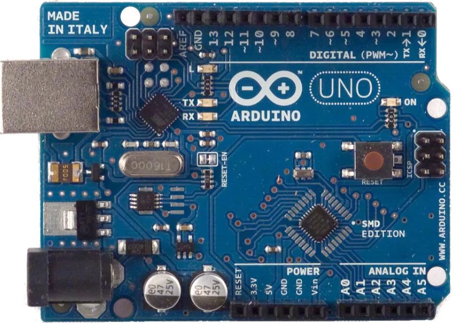
Fig-
4.7.1 Arduino Uno
Features of Arduino Uno Board
The
features of Arduino Uno ATmega328 include the following.
1.
The operating voltage is 5V
2.
The recommended input voltage will range from 7v to 12V
3.
The input voltage ranges from 6v to 20V
4.
Digital input/output pins are 14
5.
Analog i/p pins are 6
6.
DC Current for each input/output pin is 40 mA
7.
DC Current for 3.3V Pin is 50 mA
8.
Flash Memory is 32 KB
9.
SRAM is 2 KB
10.
EEPROM is 1 KB
11.
CLK Speed is 16 MHz
Arduino Uno Pin Diagram
The
Arduino Uno board can be built with power pins, analog pins, ATmegs328, ICSP
header, Reset button, power LED, digital pins, test led 13, TX/RX pins, USB
interface, an external power supply. The Arduino UNO board description is
discussed below.

Fig-
4.7.2 Arduino Uno Pin Diagram

Table no-1 Pin description
How to Use an Arduino Uno?
Arduino
Uno can detect the surroundings from the input. Here the input is a variety of
sensors and these can affect its surroundings through controlling motors,
lights, other actuators, etc. The ATmega328 microcontroller on the Arduino
board can be programmed with the help of an Arduino programming language and
the IDE (Integrated Development Environment). Arduino projects can communicate
by software while running on a PC.
Arduino Programming
Once
the Arduino IDE tool is installed in the PC, attach the Arduino board to the
computer with the help of USB cable.
Open the Arduino IDE & select the right board by choosing
Tools–>Board..>Arduino Uno, and select the right Port by choosing
Tools–>Port. This board can be programmed with the help of an Arduino
programming language depends on Wiring.
To
activate the Arduino board & flash the LED on the board, dump the program
code with the selection of Files–> Examples..>Basics..>Flash. When the
programming codes are dumped into the IDE, and then click the button ‘upload’
on the top bar. Once this process is completed, check the LED flash on the
board.
High Voltage Protection of USB
The
Arduino Uno board has a rearrangeable poly fuse that defends the USB port of
the PC from the over-voltage. Though most of the PCs have their own inner
protection, the fuse gives an additional coating of safety. If above 500mA is
given to the USB port, then the fuse will routinely crack the connection until
the over-voltage is removed.
Physical Characteristics
The
physical characteristics of an Arduino board mainly include length and width.
The printed circuit board of the Arduino Uno length and width are 2.7 X 2.1
inches, but the power jack and the USB connector will extend beyond the
previous measurement. The board can be attached on the surface otherwise case
with the screw holes.
Applications of Arduino Uno
ATmega328
The
applications of Arduino Uno include the following.
1.
Arduino Uno is used in Do-it-Yourself projects prototyping.
2.
In developing projects based on code-based control
3.
Development of Automation System
4.
Designing of basic circuit designs.
CHAPTER
NO.5
5.
SOFTWARE
In
order to program the Atmel microcontroller we will need an IDE (Integrated
Development Environment), where the programming takes place. A compiler, where our
program gets converted into MCU readable form called HEX files. An IPE
(Integrated Programming Environment), which is used to dump our hex file into
our MCUs.
1.Keil
µ vision: Keil development tools for the 8051 Microcontroller Architecture
support every level of software developer from the professional applications
engineer to the student just learning about embedded software development. When
starting a new project, simply select the microcontroller you use from the
Device Database and the µVision IDE sets all compiler, assembler, linker, and
memory options for you. Numerous example programs are included to help you get
started with the most popular embedded 8051 devices. TheKeilµVision Debugger
accurately simulates on-chip peripherals (I²C, CAN, UART, SPI, Interrupts, I/O
Ports, A/D Converter, D/A Converter, and PWM Modules) of your 8051 device.
Simulation
helps you understand hardware configurations and avoids time wasted on setup
problems. Additionally, with simulation, you can write and test applications
before target hardware is available. When you are ready to begin testing your
software application with target hardware, use the MON51, MON390, MONADI, or
FlashMON51 Target Monitors, the ISD51 In-System Debugger, or the ULINK USB-JTAG
Adapter to download and test program code on your target system.
2. Embedded
C: Embedded C is most popular programming language in software field for
developing electronic gadgets. Each processor used in electronic system is
associated with embedded software.
Embedded
C programming plays a key role in performing specific function by the
processor. In day- to-day life we used many electronic devices such as mobile
phone, washing machine, digital camera, etc. These all device working is based
on microcontroller that are programmed by embedded C
3. ISPProgrammer: Burn a Program in the Microcontroller is the process of transferring a program code to the microcontrollers memory from a compiler software. Generally, this microcontroller program is written in assembly or embedded C language. And this code is converted into hex file using Kiel IDE software, which is then transferred to the microcontroller memory using burner hardware along with dedicated software. Once the code is stored in the microcontroller, its function remains in accordance
5.1 FLOWCHART

5.2 SOURCE CODE:
//
include the library code:
#include
<LiquidCrystal.h>
//
initialize the library by associating any needed LCD interface pin
//
with the arduino pin number it is connected to
constintrs
= 2, en = 3, d4 = 4, d5 = 5, d6 = 6, d7 = 7;
LiquidCrystallcd(rs, en, d4, d5, d6, d7);
//required
variables
intprev=0,stepCount
= 0;
unsigned
long previousMillis = 0;
const
long interval = 1000;//
unsigned long currentMillis;
floatv,vout,vin;//variabls for calculating voltage
void
setup() {
pinMode(8,OUTPUT);//led
indication
//lcd code
lcd.begin(16,
2);
lcd.print("FOOT
STEP POWER");
lcd.setCursor(0,1);
lcd.print(" GENERATOR");
delay(2000);
lcd.clear();
lcd.setCursor(0,0);
lcd.print("STEP
COUNT:");
lcd.setCursor(0,1);
lcd.print("VOLTAGE:");
}
void
loop() {
v
= analogRead(A0);//analog value from voltage divider circuit
currentMillis
= millis();//calculating time
if(v!=0
and (prev == 0))
{
stepCount
+= 1; // calculating steps
digitalWrite(8,HIGH);
//led indication
lcd.setCursor(12,0);
lcd.print(stepCount);
}
else
{
if
(currentMillis - previousMillis>= 400)
{
previousMillis
= currentMillis; //time in milliseconds
digitalWrite(8,
LOW);
}
}
prev
= v;
lcd.setCursor(10,1);
//calculation
of voltage
vout
= (v*5.00)/1024.00;
vin
= vout/0.040909;
lcd.print(vin);
lcd.print("v
");
delay(200);
}
CHAPTER
NO.6
6.
APPLICATION AND FUTURE SCOPE
6.1 APPLICATIONS –
1.
Can be broadly utilized as the part of colleges, Schools, public transport
places and universities.
2.
This can be actualized in air terminals, transport stations, railroad stations.
3.
Street lights can be actualized utilizing this strategy instead of solar in the
rainy season.
4.
This framework can be actualized in swarmed places like shopping centers,
pathways and so forth.
5. It can be used in emergency power failure
situations.
6.
Application areas mainly involve Metros, street, temples, railway station and
other crowded areas.

Fig – 6.1 Applications
CHAPTER
NO.7
7.1
ADVANTAGES
·Power
generation is strolling on the step.
· No need for fuel input.
· This is the non-ordinary technique for
producing Power.
No
moving parts - long administration life.
· Self-producing-no outside power required.
· The system is reduced yet exceedingly touchy.
· It is Reliable, Economical, and Eco-Friendly.
· Less utilization of Non-sustainable power
sources
· Power is likewise produced by running or
practicing on the progression.
·Extremely
wide powerful range, free of commotion.
·No
big industries required for generation.
·Very
high-frequency response.
·Simple
to use as they have small dimensions and large measuring range.
7.2DISADVANTAGES
· The initial cost of this arrangement is
high.
· Care ought to
be taken for batteries.
· It isn't
reasonable for estimation in static conditions.
· It is not
suitable for measurement in static conditions.
· Since the
device operates with a small electric charge, they need high impedance cable
for electrical interface.
· The output may
vary according to the temperature variation of the crystal.
CHAPTER
NO.9
9.
CONCLUSION
The
project undertaken is effectively tried and actualized which is the best
conservative, reasonable vitality answer for average citizens of our country.
This can be utilized for some applications in rustic zones where control
accessibility is less or thoroughly truant .As India is a creating nation where
vitality administration is a major test for the gigantic populace. It is able
to extend this project by using same arrangement and construct in the
footsteps/speed breaker so that increase the power production rate by in fixing
school and colleges, highways etc. By utilizing this task we can drive both
A.C. and besides, D.C loads as indicated by the power we connected on the
piezoelectric sensor. This technique gives an effective power generation in
very populated nations as it diminishes control request without contamination.
As a reality, just 11% of sustainable power source adds to our essential
vitality. On the off chance that this undertaking is sent at that point not
just, we can conquer the vitality emergency issue yet, besides make a solid
worldwide ecological change.
9.1 FUTURE SCOPE-
The utilization of
wasted energy is very much relevant and important for highly populated
countries in the world in the future.
1. Flooring Tiles
Japan has already
started experimenting with the use of the piezoelectric effect impact on
generating energy. They implement a piezoelectric effect on the bus stairs.
Thus every time passenger steps on the tiles; they trigger the small vibration
that can be stored as energy in the battery. The flooring tiles are designed by
the rubber which can absorb the vibration. This vibration generates when people
are running or walking on it. Under these tiles, the piezoelectric material is
placed. They can generate electricity when the movement is felt by the
material. Simultaneously this generated energy is stored into the battery. The
generated electricity can be used for the lighting of a lamp or street light.
Energy is generated by the step of one human being is too less but if the number
of steps increases ultimately energy production also increases simultaneously.
2. Dance floors
Europe is one of the
countries which implemented and started experimenting with the use of a
piezoelectric crystal for energy generation in night clubs. The floor is then
compressed by the dancer's feet and piezoelectric materials make contact and
generate electricity which can be used as the generator in the club. The
generated electricity is nothing but 220 watts. It depends on the impact of the
dancer's feet. If constant compression of the piezoelectric crystal causes a
huge amount of energy.
3. The piezoelectric
crystals have being start better use with positive result. In India, maximum
public movement is observed in Railway stations, temples, and shopping malls;
hence this places can be used for piezoelectric crystals for generation of
electric power. Apart from all the above places a attempts are made to develop
energy from our daily life by initialing piezoelectric crystals in shoe thus in each step pie-zoelectric
crystal can be compressed which can turn enough power to charge a cell phone,
mp3 player etc.
1.
Prabaharan R, Jayramaprakash A, Vijay Anand. “Power Harvesting by Using Human
Foot Step”- International Journal of Innovative Research in Science Engineering
and Technology, vol.2, issue 7, July 2013.
2. Ramesh Raja R, Sherin Mathew.”Power
Generation from Staircase (steps)”- International Journal of Innovative
Research in Science Engineering and Technology, vol.3, Issue 1, February 2014.
3. Power Generation Using Foot Step Method.
4.
Itika Tandon, Alok Kumar. ”A Unique Step towards Generation of Electricity via
New Methodology”- International Journal of Advanced Research in Computer and
Communication Engineering, vol.3, Issue 10, October 2014.
5. Kiran Boby, Aleena Paul K, Anumol. C.V,
Josie Ann Thomas, Nimisha K.K." Footstep Power Generation Using
Piezoelectric Transducer”- International Journal of Engineering and Innovative
Technology, vol.3, Issue 10, April 2014.
6.
Footstep Energy Generation By Piezoelectric Effect: A Case Study On New Delhi
RailWay Station, International Journal of electronics & data communication.
7. Foot Step Power Generation Using
Piezoelectric Material, MathaneNitashree V., SalunkheArati L, GaikwadSayali S,
International Journal of Advanced Research in Electronics and Communication
Engineering (IJARECE) Volume 4, Issue 10, October 2015.
8.
Footstep Power Generation Using Piezo Electric Transducers, KiranBoby, Aleena
Paul K, Anumol.C.V, Josnie Ann Thomas, Nimisha K.K., International Journal of
Engineering and Innovative Technology (IJEIT) Volume 3, Issue 10, April 2014
9. Proposed Method of Foot Step Power
Generation Using Piezo Electric Sensor, Mr.A.Adhithan1, K.Vignesh,
M.Manikandan, International Advanced Research Journal in Science, Engineering
and TechnologyVol. 2, Issue 4, April 2015.
Comments
Post a Comment